Got my EspoTek Labrador Oscilloscope from Crowd Supply. It has been a long while since playing around with an Oscilloscope let alone an open hardware one like this. Here is my first look:
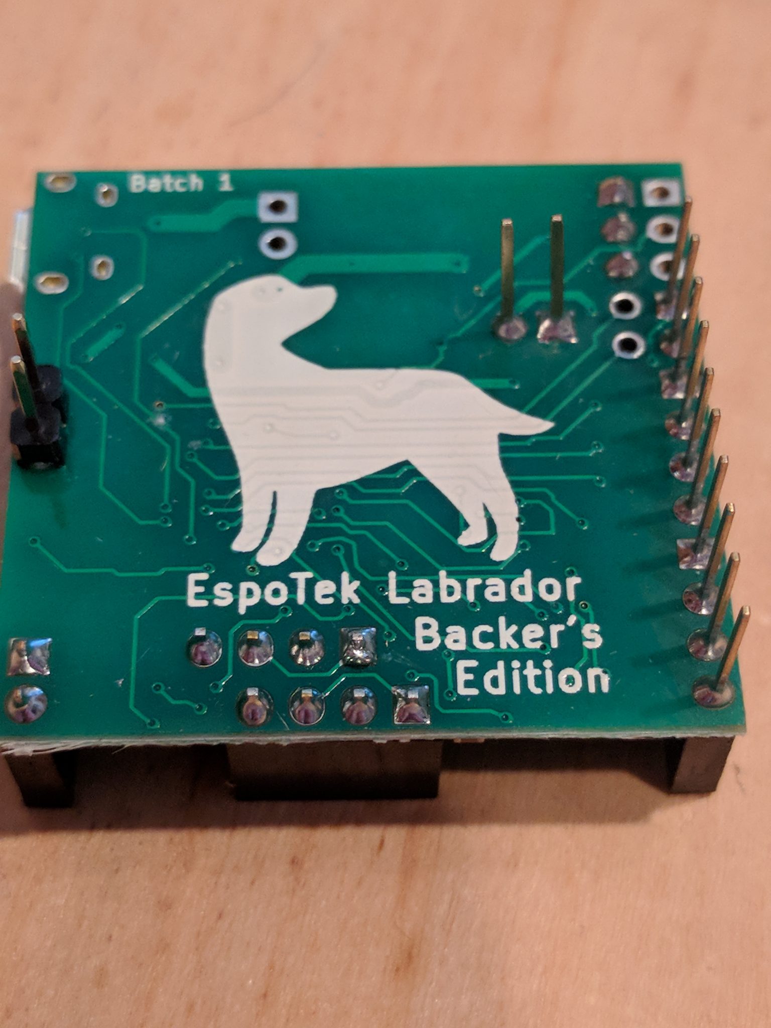
Couple of shots out of the box

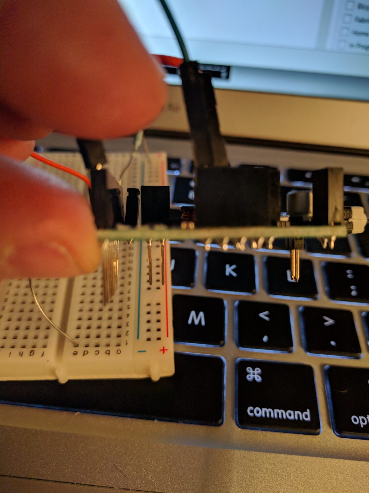
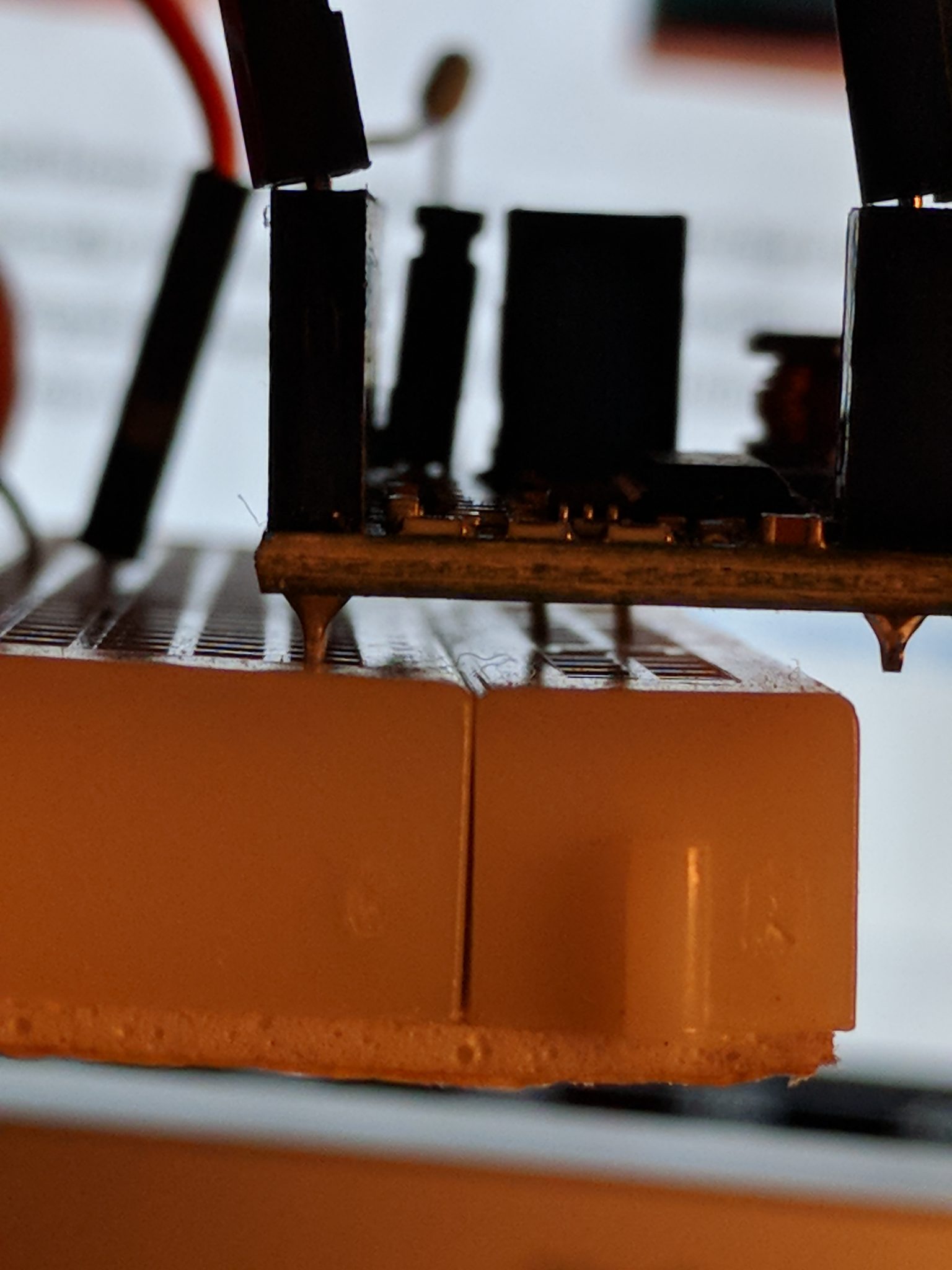
Connected to a bread board: Not absolutely necessary but I would suggest starting with it. Basically fits nicely on a standard breadboard. Note, the pins for Power Supply and the Signal Generator and "Digital Outs" line up on the bread board for a pretty handy. Do take care inserting into the breadboard as they legs are pretty long and I would say not exact but they do work.
Had to dig a bit for this but found the Pinout diagram - very helpful of course. There are no pinout descriptions on the device itself or at least any legible ones for these old eyes so keep the PinOut link handy.
First, get oscilloscope software for your device at their github repo: EspoTek Labrador Releases and get it installed. I had one issue getting the device to be recognized on my MacBook Air but a simple unplug/replug in the USB cable did the trick. There may be a sequence to follow but I have not played more with is since it started working.
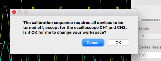
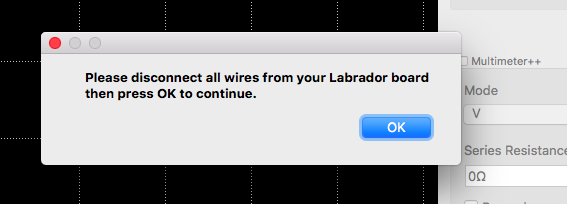
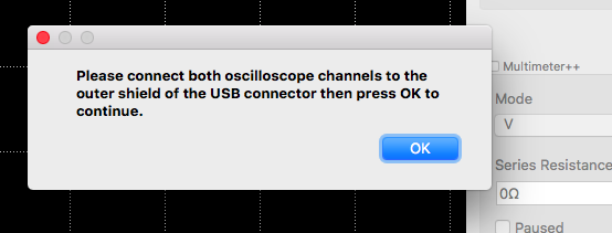
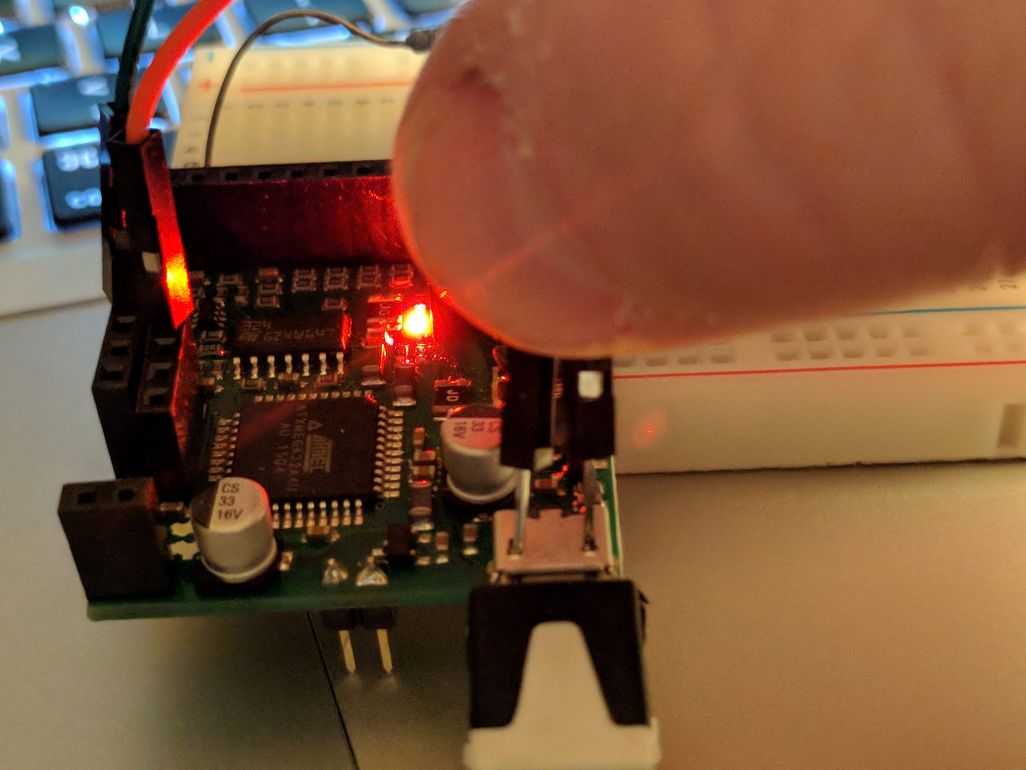
Have a couple of wires ready to calibrate it on startup. The basic calibration process require (appears you ground out the Oscilloscope CH1 and CH2 to the USB housing).

Next I basically recreated the sample from their wiki Tutorial: Connecting a Simple Circuit to the EspoTek Labrador
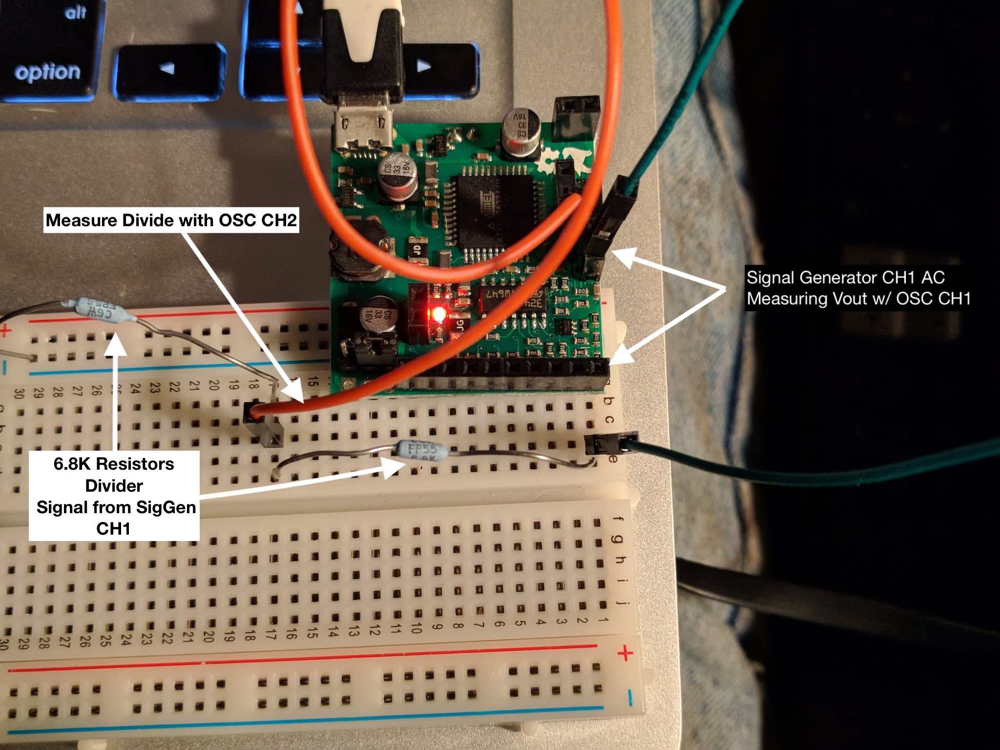

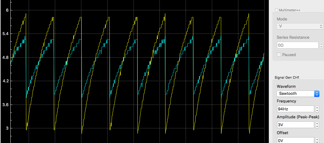
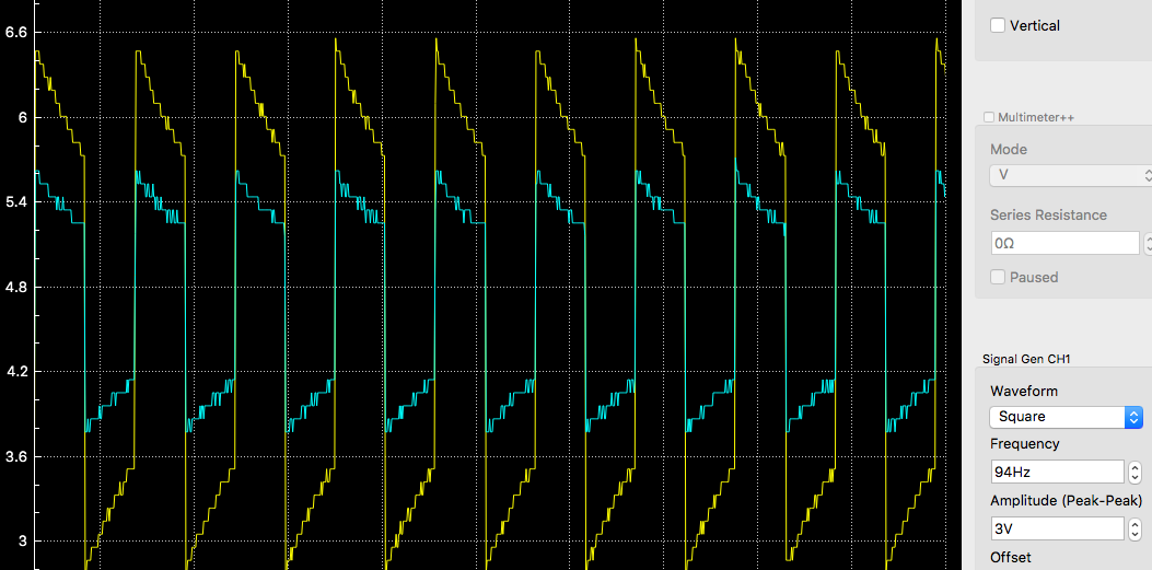
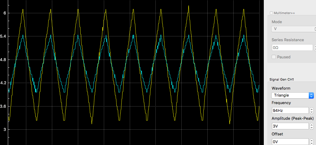
Messed around a bit with the signal generator using the same circuit: Not sure what is going on with the Square wave but the other waveforms look accurate.
All and all pretty please with the Labrador Oscilloscope. Will mess with the Multimeter and Logic Analyzer soon enough.